logo
Main Theory Technology Analitic Application Contacts
ru

Technology
Technology ...
Electroluminescence
Electroluminescence ...
Measuring
Measuring ...
Panels
Solar Panels ...
Solar charger
Solar charger ...
The conventional solar cells structure
solar cell structure
The silicon solar cells are consisting from:
  1. Front silver grid;
  2. Antireflection coating (ARC);
  3. Emitter region of semiconductor (n-type);
    р-n junction *;
  4. Base region of semiconductor (p-type);
  5. Back surface field (BSF);
  6. Aluminum rear contact ;
  7. Rear silver – aluminum contact.
* is situated between p and n regions.
The principle of solar energy transformation

The transformation of solar energy into electricity by semiconductor solar cell occurs by this way:

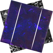
Solar light enters into semiconductor and generates electron-hole pairs, this pairs are divided by incorporated electric field (p-n junction) between emitter and base of element. The difference between cell polarities is created by this way potential. The electric current will flow if connect cell polarities to load.

At the www.pveducation.org exists animation, which schematically images the solar energy transformation process. Here is one:

The animation of transformation process.
(click button to activate)

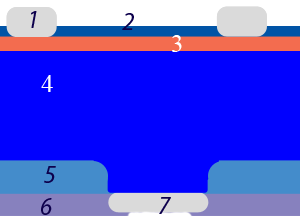
Animation description: when photon enters to semiconductor an electron-hole pair is generated. In this case it occurs in emitter region (n-type). The electron (marked as red ball) takes part in doing useful work in the electrical load while hole (marked as blue ball) is moving to the back contact of element. When hole meet electron occurs recombination (the opposite mechanism of generation).

The power losses

The power losses of solar enegy transformation can be divided by following categories:

Categories: Contribution*: Explanation:
Thermalisation 29% Part of photon energy which more than silicon band gap transforms into thermo energy.
Recombination 23% The recombination charge carriers before dividing by p-n junction.
hv lower than Eg 19% The photons, which energy less than band gap could not generate electron-hole pairs.
L less than 400 nm 5% Ultra violet spectral response losses
Shadowing 4% Frontal grid shadowing
Reflection 3% The reflection from the texture surface coated ARC
Serial resistivity 0,5% The electrical resistivity loses in the emitter and frontal contacts.

* The categories contribution depends on solar cell construction. Here are only oriented values for conventional solar cells.
Solar cell efficiency calculation
Eff = 100*Wp/(S*E)

,where:
Eff - efficiency, %;
S - element area , m2;
E - light power, W/m2 (usually 1000 W/m2);
Wp - element peak power at 25оС, W.

Example:

S = 154.7 cm2
E = 1000 W/m2
Wp =2.75 W
Eff = 100*2.75/(154.7*10-4*1000) = 17.78%
Hosted by uCoz